KiCad Nightly Reference Manual
Copyright
This document is Copyright © 2010-2024 by its contributors as listed below. You may distribute it and/or modify it under the terms of either the GNU General Public License (http://www.gnu.org/licenses/gpl.html), version 3 or later, or the Creative Commons Attribution License (http://creativecommons.org/licenses/by/3.0/), version 3.0 or later.
Toutes les marques apparaissant dans ce document appartiennent à leurs propriétaires respectifs.
Contributeurs
Jean-Pierre Charras, Fabrizio Tappero, Jon Evans, Graham Keeth.
Traduction
-
Marc Berlioux <[email protected]>, 2015-2016.
-
Francisco Dos Santos <[email protected]>, 2020. Retours
The KiCad project welcomes feedback, bug reports, and suggestions related to the software or its documentation. For more information on how to submit feedback or report an issue, please see the instructions at https://www.kicad.org/help/report-an-issue/
Software and Documentation Version
This user manual is based on KiCad 9.99. Functionality and appearance may be different in other versions of KiCad.
Documentation revision: 86e9f49c.
Introduction
KiCad is an open-source software suite for creating electronic circuit schematics and printed circuit boards (PCBs). KiCad supports an integrated design workflow in which a schematic and corresponding PCB are designed together, as well as standalone workflows for special uses. KiCad also includes several utilities to help with circuit and PCB design, including a PCB calculator for determining electrical properties of circuit structures, a Gerber viewer for inspecting manufacturing files, and an integrated SPICE simulator for inspecting circuit behavior.
KiCad runs on all major operating systems and a wide range of computer hardware. It supports PCBs with up to 32 copper layers and is suitable for creating designs of all complexities. KiCad is developed by a volunteer team of software and electrical engineers around the world with a mission of creating free and open-source electronics design software suitable for professional designers.
The latest version of this documentation is available at https://docs.kicad.org.
System Requirements
KiCad is capable of running on a wide variety of hardware and operating systems, but some tasks may be slower or more difficult on lower-end hardware. For the best experience, a dedicated graphics card and display with 1920x1080 or higher resolution is recommended.
Please check the KiCad website for the latest system requirements: https://kicad.org/help/system-requirements/
Fichiers et dossiers de KiCad
KiCad crée et utilise, pour l’édition des schéma et circuits imprimés, des fichiers (et dossiers) avec les extensions suivantes.
Many of these files include important design information, especially the project file (.kicad_pro), the schematic file(s) (.kicad_sch), and the board file (.kicad_pcb). Other files may also be necessary. Such files should always be included when distributing the project. Some files are not necessary to distribute with the project, such as the project-local settings file (.kicad_prl) or the fp-info-cache file. Files that are unnecessary to distribute are noted in the table below.
Project files
|
Project file, containing settings that are shared between the schematic and PCB |
|
Legacy (KiCad 5.x and earlier) project file.
Can be read and will be converted to a |
Schematic editor files
|
Schematic files, containing all symbol and connection information. |
|
Schematic symbol library file, containing the symbol descriptions: graphic shape, pins, fields. |
|
Schematic design block library folders. The folder itself is the library. |
|
Schematic design block folder for defining a reusable schematic design.
The folder is the design block, and contains a |
|
Simulator workbook file containing SPICE simulation setup information. |
|
Legacy (KiCad 5.x and earlier) schematic file.
Can be read and will be converted to a |
|
Legacy (KiCad 5.x and earlier) schematic library file. Can be read but not written. |
|
Legacy (KiCad 5.x and earlier) schematic library documentation. Can be read but not written. |
|
Legacy (KiCad 5.x and earlier) schematic component library cache file.
Required for proper loading of a legacy schematic ( |
|
Symbol library table: list of symbol libraries available in the schematic editor. |
|
Design block library table: list of design block libraries available in the schematic editor. |
Board editor files and folders
|
Board file containing all info but the page layout. |
|
Footprint library folders. The folder itself is the library. |
|
Footprint files, containing one footprint description each. |
|
Design rules file, containing custom design rules for a certain |
|
Legacy (KiCad 4.x and earlier) board file. Can be read, but not written, by the current board editor. |
|
Legacy (KiCad 4.x and earlier) footprint library file. Can be read by the footprint or the board editor, but not written. |
|
Footprint library table: list of footprint libraries available in the board editor. |
|
Cache to speed up loading of footprint libraries. Does not need to be distributed with the project or put under version control. |
Common files
|
Local settings for the current project; helps KiCad remember the last used settings such as layer visibility or selection filter. Does not need to be distributed with the project or put under version control. |
|
Page layout (drawing border and title block) description file. |
|
Jobset definition file containing output jobsets. |
|
Netlist file created from the schematic, and read by the board editor. Note that the recommended workflow for transferring information from the schematic to the board does not require the use of netlist files. |
|
Association between components used in the schematic and their footprints.
It can be created by the Board Editor and imported by the Schematic Editor.
Its purpose is to import changes from the board to the schematic, for users
who change footprints in the Board Editor (for instance using Exchange
Footprints command) and want to import these changes back to the schematic.
Note that the
recommended
workflow for transferring information from the board to the schematic does not
require the use of |
Fabrication and documentation files
|
Gerber files, for fabrication. |
|
Drill files (Excellon format), for fabrication. |
|
Position files (ASCII format), for automatic insertion machines. |
|
Report files (ASCII format), for documentation. |
|
Plot files (Postscript), for documentation. |
|
Plot files (PDF format), for documentation. |
|
Plot files (SVG format), for documentation. |
|
Plot files (DXF format), for documentation. |
|
Plot files (HPGL format), for documentation. |
Storing and sending KiCad files
KiCad schematic and board files contain all the schematic symbols and footprints used in the design, so you can back up or send these files by themselves with no issue. Some important design information is stored in the project file (.kicad_pro), so if you are sending a complete design, make sure to include it.
Some files, such as the project-local settings file (.kicad_prl) and the fp-info-cache file, are not necessary to send with your project. If you use a version control system such as Git to keep track of your KiCad projects, you can add these files to the list of ignored files so that they are not tracked.
Installing and Upgrading KiCad
Importing settings
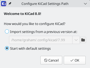
Each major release of KiCad has its own configuration, so that you may run multiple KiCad versions on the same computer without the configurations interfering. The first time you run a new version of KiCad, you will be asked how to initialize the settings:
If a previous version of KiCad is detected, you will have the option to import the settings from that version. The location of the previous configuration files is detected automatically, but you may override it to choose another location if desired.
Please note that, the schematic symbol and footprint library tables from the previous version of KiCad will not be imported.
You may also choose to start with default settings if you do not want to import settings from a previous version.
KiCad stores the settings files in a folder inside your user directory. Each KiCad version will use a different versioned subfolder. For KiCad 9, those folders are:
Windows |
|
Linux |
|
macOS |
|
Migrating files from previous versions
Modern versions of KiCad can open files created in earlier versions, but can only write files in the latest formats. This means that in general, there are no special steps to migrate files from a previous version besides opening the files. In some cases, the file extension for a file has changed from one KiCad version to the next. After opening these files, they will be saved in the new format with the new file extension. The old files will not be deleted automatically.
The schematic editor documentation describes several particular considerations for opening legacy schematics.
In general, files created or modified by one version of KiCad cannot be opened by older versions of KiCad. For this reason, it is important to keep backup copies of your projects when testing a new KiCad release, until you are confident that you will not need to use the older KiCad version anymore.
Hotkey configurations are not imported from previous versions at this time. You can manually
import hotkey configurations by copying the various *.hotkeys files from the old version
configuration directory to the new one. If you do so, please note that KiCad will not
automatically detect conflicts such as one key being assigned to multiple actions.
|
Using the KiCad project manager
The KiCad project manager is a tool which creates and opens KiCad projects and launches the other KiCad tools (schematic and board editors, Gerber viewer, and utility tools).

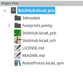
The KiCad project manager window is composed of a tree view on the left showing the files associated with the open project, and a launcher on the right containing shortcuts to the various editors and tools.
The toolbar on the left side of the window provides shortcuts for common project operations:
|
Create a new project. |
|
Open an existing project. |
|
Create a zip archive of the whole project. This includes schematic files, libraries, PCB, etc. |
|
Extract a project zip archive into a directory. Files in the destination directory will be overwritten. |
|
Refresh the tree view, to detect changes made on the filesystem. |
|
Open the project working directory in a file explorer. |
The tree view shows a list of files inside the project folder. Double-clicking on a file in the tree view will open it in the associated editor. Right-clicking on a file will open a context menu with some file manipulation commands. If the project is part of a Git repository, the tree shows icons indicating the version control status of each file and lists the active branch next to the project name.
| Only files that KiCad understands how to open are displayed in the project tree view. |
KiCad projects contain at least a project file, a schematic, and a board design. Schematics may contain multiple sheets, each in its own file, but a project can only contain a single board. KiCad expects the project file, schematic root sheet file, and board file to all have the same name.
Standalone mode
You can also run the KiCad editor tools in standalone mode, by launching them directly from your operating system’s application launcher rather than from the project manager. It is usually not recommended to run the tools in standalone mode, except for some specific situations where it is necessary, such as when importing projects from other EDA tools. When running in standalone mode, some project features are not available, including:
-
cross probing between the schematic editor and the board editor
-
design synchronization between the schematic and the board
Créer un nouveau projet
Most KiCad designs start with the creation of a project. There are two ways to create a project from the KiCad project manager: you may create an empty project, or create a project based on an existing template. This section will cover the creation of a new, empty project. Creating projects from templates is covered in the Project Templates section.
To create a new project, use the New Project… command in the File menu, click the New Project button in the top toolbar, or use the keyboard shortcut (Ctrl+N by default).
You will be prompted for a name to give your project. By default, a directory will be created for your project with the same name. For example, if you enter the name MyProject, KiCad will create the directory MyProject and the project file MyProject/MyProject.kicad_pro inside it.
If you already have a directory to store your project files in, you can uncheck the Create a new directory for the project checkbox in the New Project dialog.
| It is strongly recommended that you store each KiCad project inside its own directory. |
Once you select the name of your project, KiCad will create the following files inside the project directory:
|
KiCad project file. |
|
Main schematic file. |
|
Printed circuit board file. |
Importing a project from another EDA tool
KiCad is able to import files created by some other software packages. Some software formats can be imported as complete projects. Others can only be imported as standalone schematics or boards at the moment, and must be manually linked together into a KiCad project. Currently the following types of project are supported:
|
Eagle 6.x or newer (XML format) |
|
CADSTAR archive format |
|
EasyEDA (JLCEDA) Standard Backup |
|
EasyEDA (JLCEDA) Pro Project |
To import a project from one of these tools, choose the appropriate option from the Import Non-KiCad Project submenu of the File menu.
You will be prompted to select either a schematic or a board file in the import file browser dialog. The imported schematic and board files should have the same base file name (e.g. project.sch and project.brd). Once the requested files are selected, you will be asked to select a directory to store the resulting KiCad project.
Currently the following types of documents can be imported standalone. To import these documents, start the KiCad Schematic Editor or PCB Editor standalone (do not open the KiCad project manager first) and choose File > Import > Non-KiCad Schematic or File > Import > Non-KiCad Board File. When importing Altium projects, we recommend importing the PCB first, saving the resulting project, and then copying each schematic sheet into the project after importing it in a standalone Schematic Editor window.
|
Altium Designer, Circuit Studio, Circuit Maker schematic documents |
|
Altium Designer PCB |
|
Altium Circuit Maker PCB |
|
Altium Circuit Studio PCB |
|
P-Cad 200x ASCII PCB |
|
Fabmaster PCB |
| KiCad does not support schematics with multiple top-level sheets. When importing designs from other tools that do support this feature, each schematic sheet must be imported, and then the imported sheets must be placed as hierarchical sheets in a new KiCad project. |
Saving and loading project archives
You can archive your project’s files into a zip archive with the Archive tool (File → Archive Project…).
You can also unarchive a project using the Unarchive tool (File → Unarchive Project…). When you unarchive a project into the currently loaded project directory, the project will be reloaded automatically to reflect any changes that were in the archived version of the project.
The archive tool saves the following files from your project folder into the archive:
|
KiCad design files |
|
Legacy KiCad design files |
|
3D models |
|
Gerber files |
|
Manufacturing files |
|
Netlists |
|
Python scripts |
|
Documentation files |
|
SPICE models |
|
IBIS models |
Git integration
The KiCad Project Manager integrates with the Git version control tool for tracking changes in your projects. It can work with an existing local Git repository, clone a project from a remote repository, or create a new repository in an existing project. You can use the tool to commit changes from your project, push and pull from a remote repository, and switch branches.
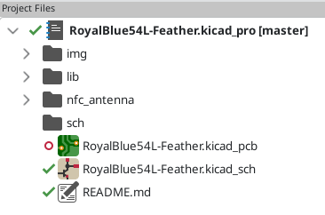
If you open a project that is already under version control with Git, i.e. it is part of an existing Git repository, you can use KiCad’s version control features to track changes in the project without any additional configuration. The active branch is displayed next to the project name, and the version control status of each file in your project is shown graphically in the project files tree. For example, the ![]() icon indicates a file is unchanged,
icon indicates a file is unchanged, ![]() indicates a file has uncommitted changes, and
indicates a file has uncommitted changes, and ![]() indicates a file is not tracked. No icons are shown if the project is not part of a Git repository.
indicates a file is not tracked. No icons are shown if the project is not part of a Git repository.
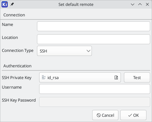
If an existing project is not already under version control, you can initialize a new Git repository in the project by right clicking on one of the files in the project files tree and clicking Version Control → Add Project to Version Control…. You must configure a remote when initializing a repository in this way. Configuring the repository requires the following information:
-
Name: A name for the repository. This field can be anything and is not used.
-
Location: The URL or file path to the remote.
-
Connection Type: The protocol for connecting to the remote. This can be HTTPS, SSH, or local (file). HTTPS connections use username and password authentication. SSH connections use a username, private key, and an optional password for the keyfile. Local connections do not use authentication. You can check the connection and authentication by clicking the Test button.
To clone an existing repository and open the cloned project, use File → Clone Project from Repository…. You can clone a remote repository using SSH or HTTPS, or clone a local repository. The configuration settings for cloning are the same as the settings for configuring a new repository and remote for an existing project.
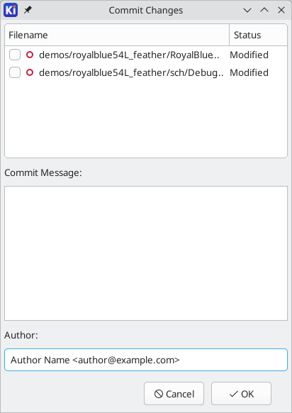
When you have made changes that you want to commit, you can commit either the entire project (right click → Version Control → Commit Project…) or a specific file (right click the file → Version Control → Commit File…). Both actions open the Commit Changes dialog, but the Commit Project action shows all changed files in the repository, while the Commit File action shows only the file that was right clicked. The Commit Changes dialog lets you select the changed files you want to include in the commit, provide a commit message and author, and commit the changes.
To push changes to the remote, right click in the project files tree and select Version Control → Push. To pull from the remote, right click and select Version Control → Pull. You can switch branches by selecting the desired branch from the Version Control → Switch to Branch menu.
Finally, you can remove version control entirely, deleting all tracked history from the local repository, by right clicking and selecting Version Control → Remove Version Control.
KiCad configuration
The KiCad preferences can always be accessed from the Preferences menu, or by using the hotkey (default Ctrl+,). The Preferences dialog is shared between the running KiCad tools. Some preferences apply to all tools, and some are specific to a certain tool (such as the schematic or board editor).
Common preferences

Accelerated graphics antialising: KiCad can use different methods to prevent aliasing (jagged lines) when rendering using a graphics card. Different methods may look better on different hardware, so you may want to experiment to find the one that looks best to you.
Fallback graphics antialiasing: KiCad can also apply antialiasing when using the fallback graphics mode. Enabling this feature may result in poor performance on some hardware.
Text editor: Choose a text editor to use when opening text files from the project tree view.
PDF viewer: Choose a program to use when opening PDF files.
Show icons in menus: Enables icons in drop-down menus throughout the KiCad user interface.
| Icons in menus are not displayed on some operating systems. |
Show scrollbars in editors: When enabled, scrollbars are displayed next to the editing canvases in each tool. When disabled, scrollbars are not shown.
Focus follows mouse between schematic and PCB editors: When enabled, the window under the mouse cursor will automatically become focused.
Icon scale: Sets the size of the icons used in menus and buttons throughout KiCad. Choose Automatic to pick an appropriate icon scale automatically based on your operating system settings.
Icon theme: Sets whether to use the icon theme designed for light window backgrounds or dark window backgrounds. The default setting of Automatic will choose the theme based on the lightness of the operating system window theme.
High-contrast mode dimming factor: Sets how much non-focused items are dimmed in high-contrast display mode.
Warp mouse to origin of moved object: When enabled, the mouse cursor will be repositioned (warped) to the origin of an object when you start a move command on that object.
First hotkey selects tool: When disabled, pressing the hotkey for a command such as Add Wire will immediately start the command at the current cursor location. When enabled, pressing the hotkey the first time will just select the Add Wire tool but will not immediately begin a wire.
Remember open files for next project launch: When enabled, KiCad will automatically re-open any files that were previously open when a project is re-opened.
Auto save: When editing schematics and board files, KiCad can automatically save your work
periodically. Set to 0 to disable this feature.
File history size: Configure the number of entries in the list of recently-opened files
3D cache file duration: KiCad creates a cache of 3D models in order to speed up the 3D viewer. You can configure how long to keep this cache before deleting old files.
Automatically backup projects: When enabled, KiCad projects will be archived to ZIP files automatically according to the settings below. The archives will be stored in a subfolder of the project folder. Backups are created when saving files in the project.
Create backups when auto save occurs: When enabled, a backup will be created every time an
automatic file save occurs (if the backup is permitted by the settings below). This setting has
no effect if the auto save interval is set to 0 (disabled).
Maximum backups to keep: When creating a new backup, the oldest backup file will be deleted to keep the total number of backup files below this limit.
Maximum backups per day: When creating a new backup, the oldest backup file created on the current day will be deleted to stay below this limit.
Minimum time between backups: If backup is triggered (for example, by saving a board file), the backup will not be created if an existing backup file is newer than this limit.
Maximum total backup size: When creating a new backup file, the oldest backup files will be deleted to keep the total size of the backup files directory below this limit.
Mouse and touchpad preferences
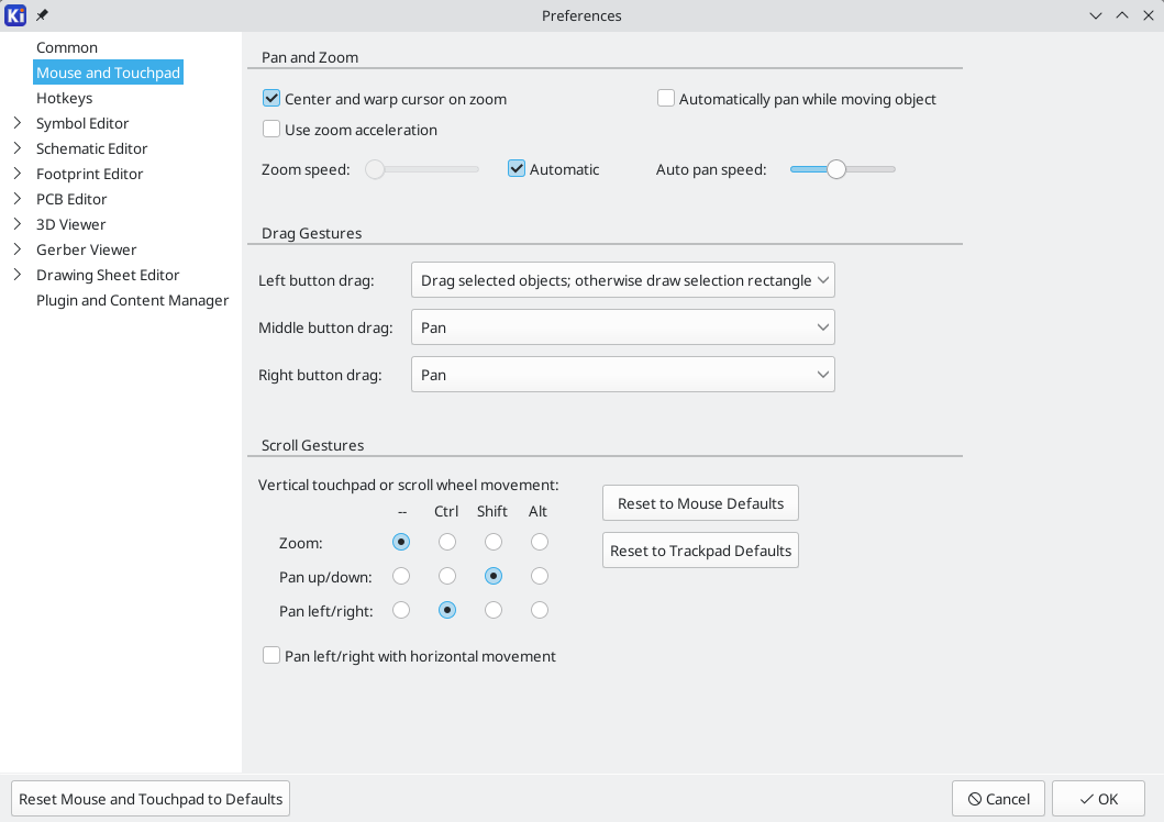
Center and warp cursor on zoom: When enabled, zooming using the hotkeys or mouse wheel will cause the view to be centered on the cursor location.
Use zoom acceleration: When enabled, scrolling the mouse wheel or touchpad faster will cause the zoom to change faster.
Zoom speed: Controls how much the zoom changes for a given amount of scrolling the mouse wheel or touchpad. Use Automatic to set a default value depending on your operating system.
Automatically pan while moving object: When enabled, the view can be panned while moving an object by moving close to the edge of the canvas.
Auto pan speed: Controls how fast the canvas pans while moving an object.
Mouse buttons: You can set the behavior of dragging the middle and right mouse buttons to zoom the view, pan the view, or have no effect. You can also set the behavior of dragging the left mouse button depending on whether or not any objects are already selected in the editing canvas.
| The left mouse button is always used for selecting and manipulating objects. |
Mouse wheel and touchpad scrolling: You can set the behavior of scrolling the mouse wheel or vertical motion of the touchpad while pressing certain modifier keys.
Pan left/right with horizontal movement: When enabled, you can pan the view using the touchpad or horizontal scroll wheel (if present on your mouse).
Hotkey preferences
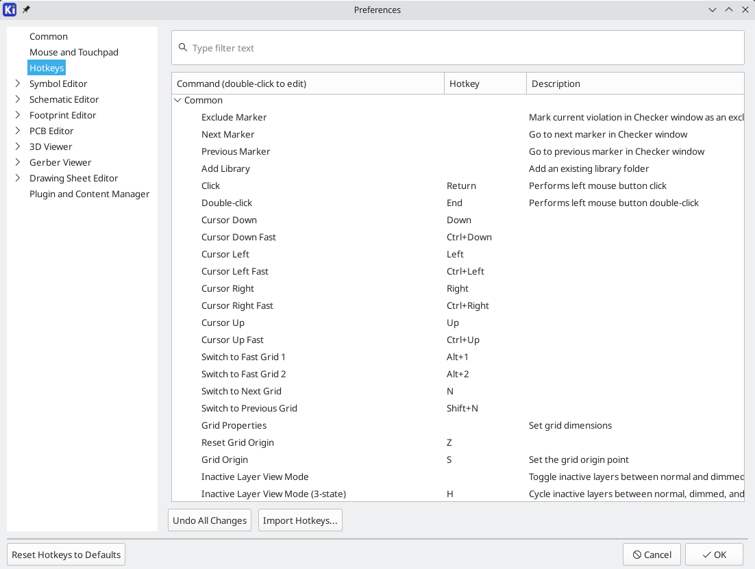
You can use this dialog to customize the hotkeys used to control KiCad. The hotkeys in the Common section are shared between every KiCad program. Hotkeys for each specific KiCad program are shown when that program is running. You can assign the same hotkey to a different action in different KiCad programs (for example, the schematic editor and the board editor), but you cannot assign a hotkey to more than one action in the same program.
There are many available commands, and so not all of them have a hotkey assigned by default. You can add a hotkey to any command by double-clicking on the command in the list. If you choose a hotkey that is already assigned to a different command, you can choose to use that hotkey on your chosen command, which will remove the hotkey assignment from the conflicting command.
Changes that you have made to hotkey assignments are shown with a * character at the end of the command name. You can undo changes to a specific command by right-clicking that command and selecting Undo Changes, or you can undo all changes with the button below the command list.
Importing hotkeys
Hotkey preferences are stored in .hotkeys files in the KiCad settings directory (see the Settings section for information about where the settings directory is on your operating system). If you have configured KiCad hotkeys the way you like on one computer, you can transfer that configuration to another computer by importing the appropriate .hotkeys file(s).
Configuration des chemins
In KiCad, one can define paths using a path variable. A few path variables are internally defined by KiCad, and can be used to define paths for libraries, 3D shapes, etc.
C’est utile quand les chemins absolus ne sont pas connus ou sont susceptibles de changer (par exemple quand vous transférez le projet sur un autre ordinateur), et aussi quand plusieurs chemins partagent une racine commune. Considérez les éléments suivants qui peuvent tous être installés à différents endroits :
-
Schematic symbol libraries
-
Footprint libraries
-
3D model files used in footprint definitions
For instance, the path to the connect.pretty footprint library, when using the KICAD9_FOOTPRINT_DIR path variable, would be defined as ${KICAD9_FOOTPRINT_DIR}/connect.pretty.
The Preferences → Configure Paths… menu allows you to define paths for some built-in KiCad path variables, and add your own path variables to define personal paths, if needed.
KiCad will automatically resolve versioned path variables from
older versions of KiCad to the value of the corresponding variable from
the current KiCad version, as long as the old variable is not explicitly
defined itself. For example, ${KICAD8_FOOTPRINT_DIR} will
automatically resolve to the value of ${KICAD9_FOOTPRINT_DIR} if there
is no KICAD8_FOOTPRINT_DIR variable defined.
|
KiCad path variables
|
Base path of KiCad’s standard 3D footprint model library files. |
|
Location for plugins, libraries, and color themes installed by the Plugin and Content Manager. |
|
Base path of KiCad’s standard footprint library files. |
|
Base path of KiCad’s standard symbol library files. |
|
Location of KiCad’s standard project template library files. |
|
Location of personal project templates. |
|
Location of personal simulation model libraries. This variable is not defined by default. |
|
Absolute path to the current project directory. This variable is set automatically and cannot be redefined. |

Paths set in the Configure Paths dialog are internal to KiCad and are not visible as environment variables outside of KiCad. They are stored in KiCad’s user configuration files.
Paths can also be set as system environment variables outside of KiCad, which will override any settings in the user’s configuration.
| You cannot override a system environment variable that has been set outside of KiCad by using the Configure Paths dialog. Any variable that has been set externally will be shown as read-only in the dialog. |
Note also that the path variable KIPRJMOD is always internally defined by KiCad, and expands to the current project absolute path. For instance, ${KIPRJMOD}/connect.pretty is always the connect.pretty folder (the footprint library) inside the current project folder. The KIPRJMOD variable cannot be changed in the Configure Paths dialog or overridden by an external environment variable.
Advanced environment variables
Some advanced environment variables can be set to customize where KiCad expects certain files to be located. By default, these locations are set based on your platform, but they can be overridden by system environment variables. These variables are not shown in the Configure Paths dialog and cannot be used in path substitutions.
Changing these variables will not result in KiCad moving any files from the default location to the new location, so if you change these variables you will need to copy any desired settings or files manually.
|
Base path of KiCad configuration files. Subdirectories will be created within this directory for each KiCad minor version. |
|
Base path of KiCad user-modifiable documents, such as projects, templates, Python scripts, libraries, etc. Subdirectories will be created within this directory for each KiCad minor version. This directory is provided as a suggested user data location, but does not need to be used. |
|
Base path of KiCad stock data, including default libraries. The data in this directory is managed by the KiCad installer or system package manager, and is not intended for user-writeable data. |
| If you modify the configuration of paths, please quit and restart KiCad to avoid any issues in path handling. |
Libraries configuration
The Preferences → Manage Symbol Libraries… menu lets you manage the list of symbol libraries (symbol library table).
Likewise, use the Preferences → Manage Footprint Libraries… menu to manage the list of footprint libraries (footprint library table).
For each type of library (symbol and footprint), there are 2 library tables: global and project specific. The global library table is located in the user configuration directory and contains a list of libraries available to all projects. The project-specific library table is optional and contains a list of libraries specific to the project. It is located in the project directory.
Jobsets
KiCad lets you configure a list of outputs that are all generated with a single click. The list of output jobs and the destinations where they will be saved is called a jobset. For example, a jobset might contain jobs to generate Gerber files, assembly data, a bill of materials, PDF plots of the schematic and PCB, while also running ERC and DRC checks, with all of the outputs saved to a compressed archive. The full list of available jobs is given below.
Each job in a jobset defines a single type of generated output, such as a bill of materials or a set of Gerbers. A job can be configured in the same way as if the output was manually generated from the schematic or board editor. The configuration for each job is stored in the jobset and remembered when you load the jobset later. Jobs are configured individually, so if you include the same type of job multiple times in a single jobset, each job will have its own independent configuration. For example, this lets you generate PDF outputs in color as well as black and white.
In addition to the jobs, jobsets also contain destinations, which define a list of jobs to run and how to store their outputs. A jobset destination can simply store the chosen jobs' output files in a specified location, or it can add the output files to a compressed archive. Each jobset destination can select a different subset of jobs from the full list of jobs in the jobset. You can run each jobset destination individually or run all jobset destinations at once. As an example, you could set up one jobset destination that generates PDFs of the board and schematic and copies them to an external location, while another destination generates the fabrication files and compresses them in a zip archive to send to the board manufacturer.
Projects can have multiple jobsets, with each jobset defining a different list of jobs and output configurations. Each jobset is stored in a .kicad_jobset file, which can be specific to a single project, copied between projects, or even stored in a central location and shared between projects.
To use a jobset, first create a new jobset file in the KiCad project manager (File → New Jobset File…) and choose a name and location for it. Alternatively, you can open an existing jobset file with File → Open Jobset File…. Jobset files that are stored in the project directory are considered part of the project and are displayed in the project file tree. You can open a jobset file in the project file tree by double clicking on it.
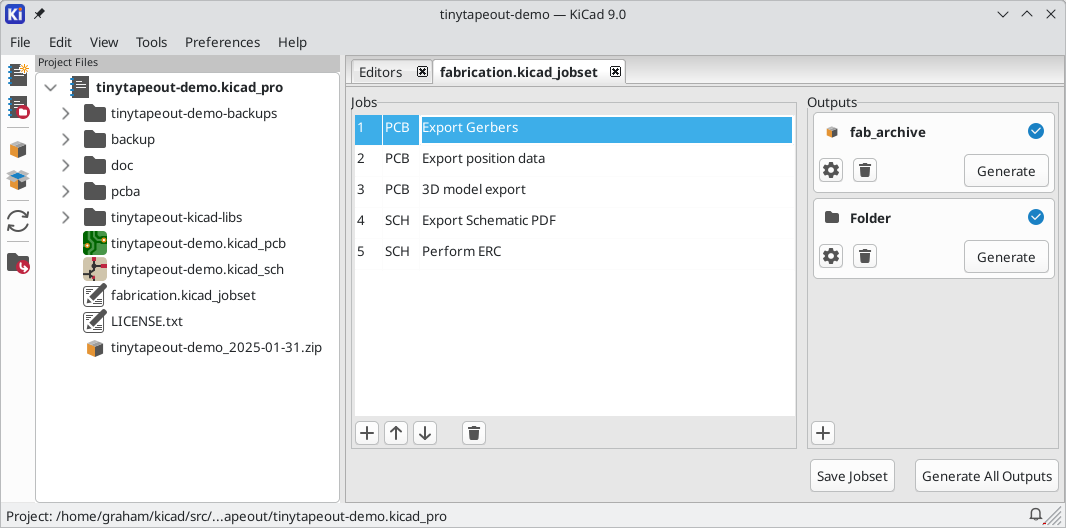
Once you create or open a jobset, it is displayed in a new tab in the project manager. The list of jobs is shown in the middle and the list of jobset destinations is shown on the right. New jobsets will not contain any jobs, but a destination is automatically created to save outputs to a folder. When you make changes to a jobset, you can save the changes by clicking the Save Jobset button.
Defining jobs
To add a new job, click the ![]() button under the Jobs list. In the Add New Job dialog that appears, select the desired type of job. You can filter which types of jobs are shown in the list by typing in the Filter textbox at the bottom.
button under the Jobs list. In the Add New Job dialog that appears, select the desired type of job. You can filter which types of jobs are shown in the list by typing in the Filter textbox at the bottom.
When you select a job and press OK, the settings dialog for that type of output will appear. Each job settings dialog provides the same options you would have if you manually generated that type of output from the schematic or board editor.
Output filenames and paths specified in job settings are relative to the jobset destination folder or archive root. You can use certain text variables, like ${PROJECTNAME}, ${CURRENT_DATE}, and project text variables.
|
When you accept the job settings dialog, the job is added to the list of jobs, where you can optionally change the new job’s description from its default. To change a job’s description or settings later, right click the job in the list and select Edit Job Description or Edit Job Settings…. Double clicking on a job also edits its settings. To remove a job, select the job and click the ![]() button. To reorder the list, select a job and move it up or down using the
button. To reorder the list, select a job and move it up or down using the ![]() or
or ![]() buttons.
buttons.
Defining jobset destinations
You cannot generate any outputs from a jobset until you add a jobset destination. One destination is created automatically when a jobset is created, but you can add as many destinations as you need.
To add a jobset destination, click the ![]() button under the Destinations list. When the Add New Destination dialog appears, select a type of destination:
button under the Destinations list. When the Add New Destination dialog appears, select a type of destination:
-
Archive saves the outputs generated by the jobs in a compressed zip archive.
-
Folder saves the outputs generated by the jobs uncompressed in a folder.
Once you have selected a type of output, the Destination options dialog appears.
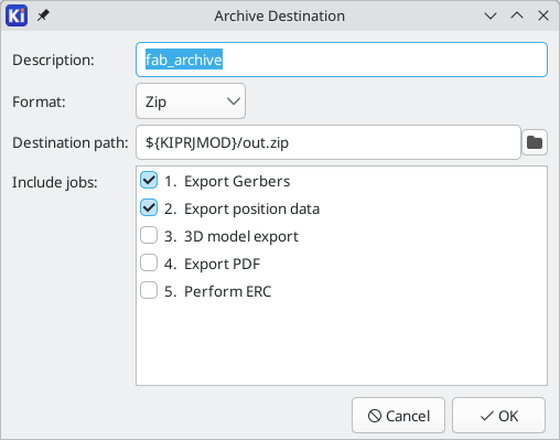
Here you can select which jobs will be run as part of this jobset destination, as well as the folder or archive name that will be used to store them. By default all jobs are enabled. You can also set a description for the destination to be displayed in the Destinations list. The output path controls where the files generated by the jobs will be saved. The path here can be absolute or relative to the project directory, and it can use path variables or certain text variables (${PROJECTNAME}, ${CURRENT_DATE}, and project text variables). Filenames defined in job configurations are relative to the jobset destination directory or archive root.
When you click OK in this dialog, the new jobset destination is added to the Destinations list. You can modify an existing jobset destination by clicking its ![]() button, or remove it by clicking its
button, or remove it by clicking its ![]() button.
button.
After configuring your jobs and destinations, you can generate an individual set of outputs by clicking the Generate button for the desired destination. You can run all destinations at once by clicking the Generate All Destinations button.
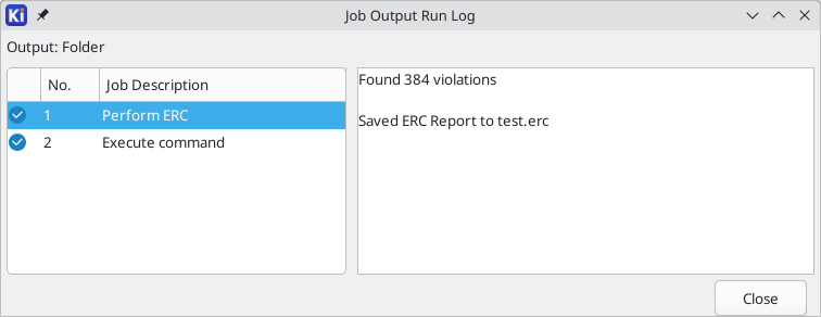
If a jobset destination runs and generates its outputs successfully, a blue check is shown that indicates the last run was successful. If a jobset destination fails to complete successfully, a red exclamation point is shown to indicate the run was not successful. Clicking on the success/failure indicator will display the Jobset Run Log dialog, which displays the status of each job in the jobset destination. Clicking on a specific job will display the logged output from that job, if there is any.
Available job types
The following types of jobs are available:
Job |
Description |
PCB: Export 3D Model |
Exports a 3D model of the board. The model format can be STEP, GLB (binary glTF), XAO, BREP (OCCT), PLY, or STL. |
PCB: Export Drill Data |
Exports a drill file from the board. |
PCB: Export DXF |
Exports the board design to a DXF file. |
PCB: Export Gencad |
Exports the board design in GenCAD format. |
PCB: Export Gerbers |
Exports the board design to Gerber files, with one file per selected layer. |
PCB: Export IPC-2581 |
Exports the board design in IPC-2581 format. |
PCB: Export ODB++ |
Exports the board design in ODB++ format. |
PCB: Export PDF |
Exports the board design to PDF files, with one file per selected board layer. You can also generate a single PDF with multiple layers depending on the plot configuration. |
PCB: Export Position Data |
Exports a position (component placement) file from the board. |
PCB: Export SVG |
Exports the board design to a SVG file. |
PCB: Perform DRC |
Performs a Design Rule Check on the board and generates a report. If DRC violations are found, this job can optionally report a job failure. |
PCB: Render |
Generates a raytraced rendering of the 3D model of the board as a PNG or JPG file. |
Schematic: Export DXF |
Exports the schematic to a DXF file. |
Schematic: Export HPGL |
Exports the schematic to a HPGL file. |
Schematic: Export Netlist |
Exports a netlist from the schematic, with various formats available. |
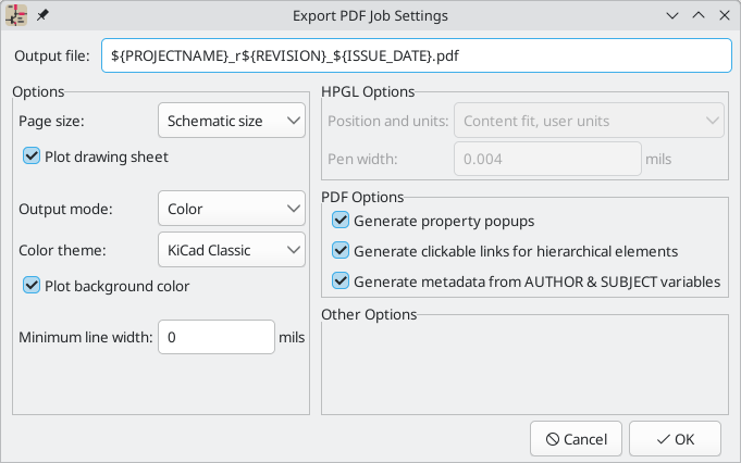
Schematic: Export PDF |
Exports the schematic to a PDF file. |
Schematic: Export Postscript |
Exports the schematic to a PostScript file. |
Schematic: Export SVG |
Exports the schematic to a SVG file. |
Schematic: Generate Bill of Materials |
Exports a bill of materials from the schematic. |
Schematic: Perform ERC |
Performs an Electrical Rule Check on the schematic and generates a report. If ERC violations are found, this job can optionally report a job failure. |
Special: Copy Files |
Copies the specified file to the specified location. A failure to copy the files can optionally cause the output job to fail. You can control whether files in the output location should be overwritten or not. |
Special: Execute Command |
Executes an arbitrary command. Output from the command can optionally be logged to a file. You can either ignore non-zero output codes or cause them to fail the output job. |
Modèles de projet
L’utilisation de modèle facilite l’initialisation d’un projet en pré-réglant certains paramètres. Un template peut contenir un circuit imprimé avec ses dimensions déjà définies, des connecteurs déjà positionnés, des règles de conception, des éléments schématique, etc… Un schéma ou circuit imprimé complet peut également être inclus comme point de départ pour un nouveau projet.
Utilisation des modèles
The File → New Project from Template menu will open the Project Template Selector dialog:
Un clic sur l’icône d’un modèle affiche ses informations, un clic sur le bouton de validation crée un nouveau projet. Les fichiers du modèle sont copiés dans le répertoire du projet et renommés pour correspondre au nom du projet.

Template locations
KiCad looks for system templates in the path defined in the KICAD9_TEMPLATE_DIR path variable, and user templates in the path defined in KICAD_USER_TEMPLATE_DIR. However, you can browse for templates in an arbitrary directory using the Folder control at the top of the dialog.
Créer des modèles
A KiCad template is simply a directory containing the template project files, as well as some required metadata for the template in a subdirectory named meta. The name of the directory containing the template files determines the name of the template. When you create a project from a template, KiCad copies the template files to the new project directory, renaming them to match the new project name as described below.
All files in the template are copied, with two exceptions:
-
Files with names beginning with the
.character (dotfiles) are not copied. There is a special case for files named.gitignoreor.gitattributes, which are copied if they exist. -
The
metadirectory is not copied
The meta directory must contain an HTML file named info.html, which is displayed in the KiCad template browser and should contain basic information describing the template. Basic HTML features are supported, including images. Any images referenced by info.html should also be stored in the meta directory.
The <title> tag determines the name of the template that is displayed during template selection. Note that the project template name will be cut off if it’s too long. This display name does not need to be the same as the template directory name.
Here is a sample info.html file:
<!DOCTYPE HTML PUBLIC "-//W3C//DTD HTML 4.0 Transitional//EN">
<HTML>
<HEAD>
<META HTTP-EQUIV="CONTENT-TYPE" CONTENT="text/html;
charset=windows-1252">
<TITLE>Raspberry Pi - Expansion Board</TITLE>
</HEAD>
<BODY LANG="fr-FR" DIR="LTR">
<P>This project template is the basis of an expansion board for the
<A HREF="http://www.raspberrypi.org/" TARGET="blank">Raspberry Pi $25
ARM board.</A> <BR><BR>This base project includes a PCB edge defined
as the same size as the Raspberry-Pi PCB with the connectors placed
correctly to align the two boards. All IO present on the Raspberry-Pi
board is connected to the project through the 0.1" expansion
headers. <BR><BR>The board outline looks like the following:
</P>
<P><IMG SRC="brd.png" NAME="brd" ALIGN=BOTTOM WIDTH=680 HEIGHT=378
BORDER=0><BR><BR><BR><BR>
</P>
<P>(c)2012 Brian Sidebotham<BR>(c)2012 KiCad Developers</P>
</BODY>
</HTML>Finally, meta can optionally contain an image named icon.png, which will be used as the template’s icon in the template selection dialog. The icon should be a 64 x 64 pixel PNG image.
Template file renaming
All files and directories in a template are copied to the new project path when a project is created using a template, except meta and any dotfiles. Files and directories containing the template directory name will be renamed with the new project file name.
For example, using a template named example (left) to create a project named newproject (right), with renamed files shown in bold:
Files in template example directory |
Files created in project newproject directory |
|---|---|
|
|
A template does not need to contain a complete project. If a required project file is missing, KiCad will create the file using the default create project behavior:
Files in template example directory |
Files created in newproject directory |
|---|---|
|
|
As an exception to the template name renaming rule, if the template contains one project file (.kicad_pro) and its name doesn’t match the template name, KiCad will do the renaming based on that project file name instead:
Files in template example directory |
Files created in newproject directory |
|---|---|
|
|
| It is not recommended to create a template with multiple project files. |
Plugin and Content Manager
| This section of the KiCad documentation has not yet been written. We appreciate your patience as our small team of volunteer documentation writers work to update and expand the documentation. |
Actions reference
Below is a list of every available action in the KiCad Project Manager: a command that can be assigned to a hotkey.
KiCad Project Manager
The actions below are available in the KiCad Project Manager. Hotkeys can be assigned to any of these actions in the Hotkeys section of the preferences.
| Action | Default Hotkey | Description |
|---|---|---|
Close Project |
Close the current project |
|
Image Converter |
Ctrl+B |
Convert bitmap images to schematic or PCB components |
Drawing Sheet Editor |
Ctrl+Y |
Edit drawing sheet borders and title block |
Footprint Editor |
Ctrl+F |
Edit PCB footprints |
PCB Editor |
Ctrl+P |
Edit PCB |
Schematic Editor |
Ctrl+E |
Edit schematic |
Symbol Editor |
Ctrl+L |
Edit schematic symbols |
Clone Project from Repository… |
Clone a project from an existing repository |
|
New Project from Template… |
Ctrl+T |
Create new project from template |
New Project… |
Ctrl+N |
Create new blank project |
Open Demo Project… |
Open a demo project |
|
Open Project… |
Ctrl+O |
Open an existing project |
Open Text Editor |
Launch preferred text editor |
|
Plugin and Content Manager |
Ctrl+M |
Run Plugin and Content Manager |
Calculator Tools |
Run component calculations, track width calculations, etc. |
|
Gerber Viewer |
Ctrl+G |
Preview Gerber output files |