生成输出
打印
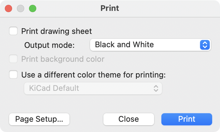
KiCad 可以使用 文件 → 打印… 将原理图发送到标准打印机。
打印选项
-
Print drawing sheet: Include the drawing sheet border and title block in the printed schematic.
-
Output mode: Print the schematic in color or black and white.
-
Print background color: Include the background color in the printed schematic. This option is only enabled when printing in color.
-
Use a different color theme for printing: Select a different color scheme for printing than the one selected for display in the Schematic Editor.
-
Page Setup…: Opens a page setup dialog for setting paper size and orientation.
-
Close: Closes the dialog without printing.
-
Print: Opens the system print dialog.
| 打印时使用平台及打印机特有的驱动程序,可能会产生意想不到的结果。当打印到一个文件时,建议使用 绘图 而不是 打印。 |
绘图
KiCad 可以使用 文件 → 绘图… 将原理图绘制到文件中。
支持的输出格式是 Postscript、PDF、SVG、DXF 和 HPGL。
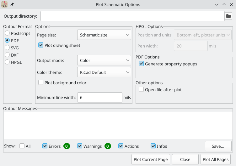
输出信息 窗格显示有关生成文件的信息。 可以用复选框显示或隐藏不同种类的信息,还可以用 保存… 按钮将信息保存到文件中。
点击绘制当前页 按钮绘制原理图的当前页。绘制全部页面 按钮可以绘制原理图的所有页面。每一页都会生成一个文件,但 PDF 输出除外,它将原理图的每一页作为单独的一页绘制在一个 PDF 文件中。
绘制选项
-
Output directory: Specify the location to save plotted files. If this is a relative path, it is created relative to the project directory. This path can use text variables, including both project text variables and built-in text variables.
-
Output Format: Select the format to plot in. Some formats have different options than others.
-
Page size: Sets the page size to use for the plotted output. This can be set to match the schematic size or to another sheet size.
-
Plot drawing sheet: Include the drawing sheet border and title block in the printed schematic.
-
Output mode: Sets the output to color or black and white. Not all output formats support color.
-
Color theme: Selects the color theme to use for the plotted output.
-
Plot background color: Includes the schematic background color in the plotted output. The background color will not be plotted if the output format does not support color or the output mode is black and white.
-
Minimum line width: Selects the minimum width for lines. Any lines narrower than this width will be plotted with this minimum width.
-
Position and units: Sets the plotter origin and units. This option only applies for HPGL output.
-
Pen width: Sets the plotter’s pen width. This option only applies for HPGL output.
-
Generate property popups: Enables the interactive PDF features described below. This option only applies for PDF output.
-
Generate clickable links for hierarchical elements: Enables clickable hierarchical sheets, hierarchical sheet pins, and hierarchical labels. When enabled, clicking a hierarchical sheet or sheet pin in the PDF will open the PDF page for that subsheet. Clicking a hierarchical label will open the page for the parent sheet. If Generate property popups is also enabled, links will be generated instead of property popups for hierarchical sheets, pins, and labels (i.e. this option takes priority). This option only applies for PDF output.
-
Generate metadata from AUTHOR and SUBJECT variables: Sets the Author and Subject PDF document properties for the generated PDF based on the
AUTHORandSUBJECTproject text variables, if you have defined them. This option only applies for PDF output. -
Open file after plot: automatically opens the plotted output file when plotting is complete.
PDF 交互功能
Plotted PDFs can optionally have several interactive features.
-
可以点击超链接。
-
目录中填充了原理图页以及每张页面中的符号和层次标签。
-
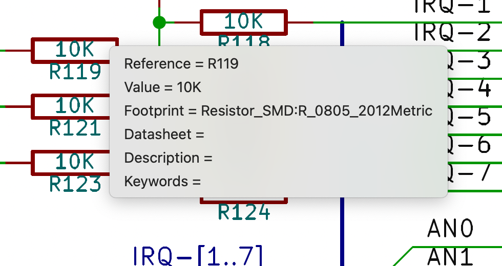
点击原理图对象会弹出一个包含相关信息的菜单。
-
符号显示其符号字段。
-
Hierarchical subsheets display their sheetname and filename, as well as an option to enter the sheet itself. This is replaced by a direct link to the subsheet if the Generate clickable links for hierarchical elements option is enabled.
-
标签显示已解决的网络和网络类。
-
总线显示其成员。
-
| Some of these features are not supported in all PDF readers. The clickable links generated by the Generate clickable links for hierarchical elements option are more widely supported than other interactive features. |
Generating a bill of materials
KiCad 可以生成物料清单,列出设计中的所有元件。物料清单是可配置的:您可以选择包括哪些元件、元件的排序方式、包括哪些符号字段和顺序,以及输出格式。
使用《符号字段表,符号字段表》导出物料清单。作为打开此对话框的 导出 选项卡的快捷方式,您可以选择* 工具 → 生成物料清单…* ,或使用顶部工具栏上的 ![]() 按钮。
按钮。
物料清单的内容在 编辑 选项卡中配置。导出 BOM 文件的格式在 导出 选项卡中配置。按下对话框底部的 导出 按钮后,BOM 即被写入。
BOM 内容
The exported BOM will contain exactly the components (rows) and fields (columns) shown in the Edit tab, with the same grouping and sorting. Components with the Exclude from BOM attribute set are hidden in the Edit tab and not included in the BOM export unless the Show 'Exclude from BOM' box is checked. Components with the DNP (do not populate) attribute set can be optionally excluded from both the table in the Edit tab and the exported BOM by checking the Exclude DNP box. You can also limit the displayed components to those in the current sheet, the current sheet and all of its subsheets, or the entire schematic by adjusting the Scope settings.
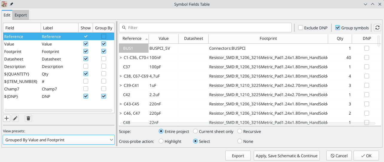
选中 显示 框的字段将作为列包含在物料清单中,选中按 分组 框的字段用于将元件分组。 如果元件的所有按 分组 字段都相同,且选中了 分组符号 框,则元件会被分组到同一行中。您可以为每个字段设置一个任意的列名,并通过拖动列头对列重新排序。
预置可用于配置字段列表。预置可存储显示的字段、用于分组的字段以及列顺序。 您可以创建并保存自己的预置,也可以使用多个默认预置之一。 自定义预置可以在此对话框或 《原理图设置,原理图设置》 对话框中删除。
内置预设 "按值分组" 和 "按值和封装分组" 复制了《旧版 BOM 脚本,旧版 BOM 脚本》,而 "属性" 只显示参考和值字段以及 DNP、从电路板排除、从仿真排除和从 BOM 排除属性。
Some virtual fields are available that may be useful in BOM exports. Adding a field in the Symbol Fields Table beginning with a text variable will not create a new field in the symbols, but will create a special column in the table and BOM with auto-generated values for each component. The following variables may be especially useful for creating virtual fields in custom BOM formats:
-
${QUANTITY}创建一个字段,其中包含该元件的分组实例数。 -
${ITEM_NUMBER}创建一个包含 BOM 中元件行号的字段。 -
${SYMBOL_NAME}creates a field that contains the name of the schematic symbol. -
${SYMBOL_LIBRARY}creates a field that contains the name of the schematic symbol library. -
${DNP}创建一个带有复选框的字段,用于控制组件的 DNP 属性。在 BOM 中,如果元件的 DNP 属性已设置,则该字段解析为字符串 "DNP",否则解析为空字符串。 -
`${EXCLUDE_FROM_BOARD}`创建了一个带有复选框的字段,用于控制元件的从电路板排除属性。在 BOM 中,如果元件的电路板排除属性已设置,则该字段解析为字符串 "电路板排除",否则解析为空字符串。
-
`${EXCLUDE_FROM_SIM}`创建一个带有复选框的字段,用于控制元件的 "从仿真中排除 " 属性。在 BOM 中,如果与元件的 "从仿真中排除" 属性已设置,则该字段解析为字符串 "从仿真中排除",否则解析为空字符串。
-
${EXCLUDE_FROM_BOM}创建一个带有复选框的字段,用于控制元件的 BOM 排除属性。设置了排除在 BOM 之外属性的元件不会包含在 BOM 中。
Other text variables are also available.
The full functionality of the Edit tab, including virtual field behavior, is explained in more detail in the Symbol Fields Table documentation.
BOM format
导出 选项卡包含有关 BOM 输出文件格式的设置,并显示原始 BOM 输出文件的预览。
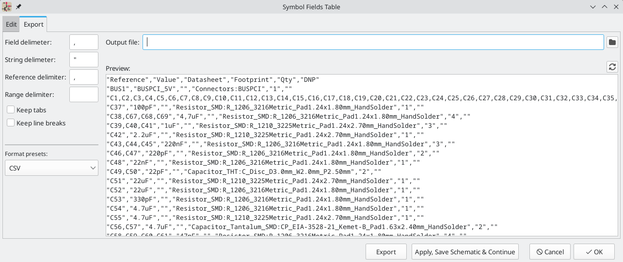
您可以在顶部指定输出文件。按下 导出 按钮将把 BOM 写入该文件路径。该路径可以包含 《文本变量,文本变量》。
左侧的设置控制 BOM 信息在文件中的格式。您可以更改字段之间的分隔符、围绕每个字段的分隔符、分隔引用序列的分隔符(例如,R1,R3 中的逗号)以及引用范围的分隔符(例如,R1-R3 中的破折号)。如果没有给出范围分隔符,则不会使用范围: 例如,R1-R3 将被写成`R1,R2,R3`,假定 , 为引用分隔符。根据 保留制表符 和 保留换行符 的设置,可以保留或删除字段中的制表符和换行符。
有多种默认格式预设可供选择。您可以选择逗号分隔值 (CSV) 格式、制表符分隔值 (TSV) 格式或分号分隔格式。您还可以创建和保存自己的预设。自定义预置可在此对话框或 《示意图设置,示意图设置》 对话框中删除。
Legacy BOM generation
以前版本的 KiCad 使用外部脚本将设计信息处理成所需的输出格式。选择 工具 → 生成传统物料清单… ,仍可使用此物料清单生成工具。

Several BOM generator scripts are included with KiCad, and users can also create their own. BOM generator scripts generally use Python or XSLT, but other tools can be used as long as you can specify a command line for KiCad to execute when running the generator.
您可以在 BOM 发生器脚本 列表中选择要使用的 BOM 生成器。 对话框的其余部分显示所选生成器的信息。您可以用 生成器昵称 文本框来改变生成器的显示名称。
右边的窗格显示所选脚本的信息。当生成器被执行时,右边的窗格会显示脚本的输出。
底部的文本框包含了 KiCad 用来执行生成器的命令。当选择脚本时,该文本框会自动填充,但对于某些生成器来说,该命令可能需要手工编辑。当关闭 BOM 工具时,KiCad 会保存每个生成器的命令行,因此定制的命令行会被保留下来。关于命令行的更多细节,请参阅 高级文档。
在 Windows 下,BOM 生成器对话框有一个额外的 *显示控制台窗口*选项。当这个选项未被选中时,BOM 生成器在一个隐藏的控制台窗口中运行,任何输出都会被重定向并打印在对话框中。当该选项被选中时,BOM 生成器在一个可见的控制台窗口中运行,如果生成器插件提供了一个图形用户界面,这可能是必要的。
BOM 生成器脚本
By default, the legacy BOM tool presents three output script options.
-
bom_csv_grouped_extraoutputs a CSV with a single section containing every component in the design. Components are grouped by value, footprint, DNP (do not populate), and any additional fields that are specified on the command line. To specify extra fields, add the desired field names as quoted strings at the end of the command line. For example, to include theMPNfield, the end of the command line would be:<path to script>/bom_csv_grouped_extra.py "%I" "%O.csv" "MPN". The columns in the BOM are:-
行编号
-
位号
-
数量
-
值
-
封装
-
不安装
-
指定的额外字段
-
-
bom_csv_grouped_by_value输出的CSV有两个部分。第一部分包含了设计中的每个元件,每行都有一个元件。 第二部分也包含每个元件,但元件是按符号名称、值、封装和 DNP(不安装)分组的。BOM 中的列是:-
行编号
-
数量
-
位号
-
值
-
符号库和符号名称
-
封装
-
数据手册
-
不安装
-
任何其他符号字段
-
-
bom_csv_grouped_by_value_with_fp输出一个 CSV,其中有一个单独的部分,包含设计中的每个元件。元件按值、封装和 DNP(不安装)进行分组。BOM 中的列是:-
位号
-
数量
-
值
-
符号名称
-
封装
-
符号描述
-
供应商
-
不安装
-
额外的生成器脚本与 KiCad 一起安装,但默认情况下不会在生成器脚本列表中填入。这些脚本的位置取决于操作系统,并可能根据安装位置而有所不同。
| Operating System | Location |
|---|---|
Windows |
|
Linux |
|
macOS |
|
通过点击 ![]() 按钮,可以在 BOM 生成器脚本列表中添加其他脚本。点击
按钮,可以在 BOM 生成器脚本列表中添加其他脚本。点击 ![]() 按钮,可以删除脚本。
按钮,可以删除脚本。![]() 按钮在文本编辑器中打开所选的脚本。
按钮在文本编辑器中打开所选的脚本。
关于创建和使用自定义 BOM 生成器的更多信息,请参见 高级文档。
从 PCB 编辑器导出 BOM
The PCB Editor can export a BOM through File → Fabrication Outputs → BOM…. This method provides no control over the output format and does not include all symbol information, but is useful for PCB-only workflows that do not involve a schematic. In general, it is recommended to use the schematic editor’s BOM export tool instead.
生成网表
网表是一个描述符号引脚之间电气连接的文件。 这些连接被称为网络。网表文件包含:
-
符号及其引脚的列表。
-
符号引脚之间的连接(网络)列表。
存在许多不同的网表格式。有时符号表和网表是两个独立的文件。网表是使用原理图设计软件的基础,因为网表建立了与其他电子 CAD 软件,如 PCB 布局软件、仿真器和可编程逻辑编译器的联系。
KiCad 支持几种网表格式:
-
KiCad 格式,可由 KiCad PCB 编辑器导入。然而,应该使用 "从原理图更新 PCB" 工具而不是将 KiCad 网表导入 PCB 编辑器。
-
OrCAD PCB2 格式,用于 OrCAD 设计 PCB。
-
Allegro format, for designing PCBs with Allegro.
-
PADS format, for designing PCBs with PADS.
-
CADSTAR 格式,用于 CADSTAR 设计 PCB。
-
Spice 格式,用于各种外部电路仿真器。
| 在 KiCad 5.0 及以后的版本中,将设计从原理图编辑器转移到 PCB 编辑器时,没有必要创建网表。推荐使用 "从原理图更新PCB" 工具。 |
| 其他使用网表的软件工具可能对元件名称、引脚、网络和其他字段中的空格和特殊字符有限制。为了兼容性,请注意其他工具中的这种限制,并相应地命名元件、网络等。 |
网表格式
网表是通过导出网表对话框(文件 → 导出 → 网表…)导出的。
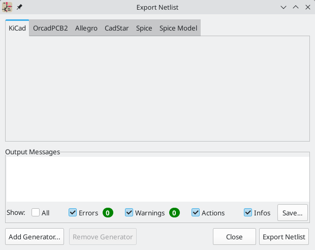
KiCad supports exporting netlists in several formats: KiCad, OrcadPCB2, Allegro, PADS, CADSTAR, Spice, and Spice Model. Each format can be selected by selecting the corresponding tab at the top of the window. Some netlist formats have additional options.
点击 导出网表 按钮,会提示输入网表文件名并保存网表。
| 对于大型原理图,网表的生成可能需要几分钟。 |
其他网表格式的自定义生成器可以通过点击 添加生成器… 按钮添加。自定义生成器是由 KiCad 调用的外部工具,例如 Python 脚本或 XSLT 样式表。关于自定义网表生成器的更多信息,请参见添加自定义网表生成器章节。
Spice 网表格式
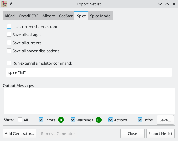
Spice 网表格式提供了几个选项。
-
当选择 使用当前图纸作为根图纸 时,只有当前页图纸导出到子电路模型中。否则,所有原理图图纸将被导出。
-
The Save all voltages option adds a
.save allcommand to the netlist, which causes the simulator to save all node voltages. -
The Save all currents option adds a
.probe allicommand to the netlist, which causes the simulator save all node currents. -
The Save all power dissipations adds
.probecommands to save the power dissipation in each component. -
The Save all digital event data removes the
esave nonecommand from the netlist, which causes digital event data to be saved. Digital event data may consume a lot of memory.
| 不同仿真工具之间的行为可能有所不同。 |
无源符号值会自动调整,以便与各种 Spice 仿真器兼容。具体而言:
-
μandMas unit prefixes are replaced withuandMeg, respectively -
Units are removed (e.g.
4.7kΩis changed to4.7k) -
RKM 格式的数值被改写为与 Spice 兼容(例如,
4u7被改成4.7u)
Spice 网表导出器还提供了一种简单的方法,可以用外部仿真器对生成的网表进行仿真。这对于在不使用KiCad 的内部 ngspice 仿真器的情况下运行仿真,或者使用 KiCad 的仿真器工具不支持的选项运行 ngspice 仿真是很有用的。
Enter the path to the external simulator in the text box, with %I representing the generated netlist. Check the run external simulator command box to generate the netlist and automatically run the simulator.
默认的仿真器命令(spice "%I")必须调整为指向系统上安装的仿真器。
|
Spice 仿真器预期仿真命令(.PROBE, .AC, .TRAN 等)包含在网表中。原理图中包含的任何以句号(.)开始的文本行都将被包含在网表中。如果一个文本对象包含多行,只有以句号开头的行将被包含在内。
根据原理图中符号的 Spice 模型设置,用于包括模型库文件的 .include 指令被自动添加到网表。
Spice 模型网表格式
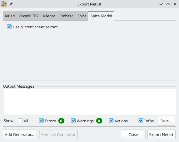
KiCad 还可以将原理图的网表导出为 Spice 子电路模型,这可以包含在一个单独的 Spice 仿真中。原理图中的任何层次标签都被用作子电路模型的引脚。模型中的每个引脚都有批注,描述该引脚的电气方向:
-
输入的层次标签被映射到一个输入的批注上 -
输出的层次化标签被映射到输出批注上 -
双向层次标签被映射到输入输出批注上 -
三态的层次标签被映射到三态批注上 -
被动层次标签被映射到被动批注上
当选择 使用当前图纸作为根图纸 时,只有当前页图纸导出到子电路模型中。否则,所有原理图图纸将被导出。
网表示例
下面是 KiCad 仿真示例的 sallen_key 工程的原理图。
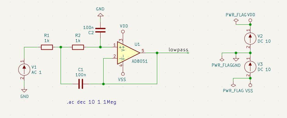
该原理图的 KiCad 格式网表如下:
(export (version "E")
  (design
    (source "/usr/share/kicad/demos/simulation/sallen_key/sallen_key.kicad_sch")
    (date "Sun 01 May 2022 03:14:05 PM EDT")
    (tool "Eeschema (6.0.4)")
    (sheet (number "1") (name "/") (tstamps "/")
      (title_block
        (title)
        (company)
        (rev)
        (date)
        (source "sallen_key.kicad_sch")
        (comment (number "1") (value ""))
        (comment (number "2") (value ""))
        (comment (number "3") (value ""))
        (comment (number "4") (value ""))
        (comment (number "5") (value ""))
        (comment (number "6") (value ""))
        (comment (number "7") (value ""))
        (comment (number "8") (value ""))
        (comment (number "9") (value "")))))
  (components
    (comp (ref "C1")
      (value "100n")
      (libsource (lib "sallen_key_schlib") (part "C") (description ""))
      (property (name "Sheetname") (value ""))
      (property (name "Sheetfile") (value "sallen_key.kicad_sch"))
      (sheetpath (names "/") (tstamps "/"))
      (tstamps "00000000-0000-0000-0000-00005789077d"))
    (comp (ref "C2")
      (value "100n")
      (fields
        (field (name "Fieldname") "Value")
        (field (name "SpiceMapping") "1 2")
        (field (name "Spice_Primitive") "C"))
      (libsource (lib "sallen_key_schlib") (part "C") (description ""))
      (property (name "Fieldname") (value "Value"))
      (property (name "Spice_Primitive") (value "C"))
      (property (name "SpiceMapping") (value "1 2"))
      (property (name "Sheetname") (value ""))
      (property (name "Sheetfile") (value "sallen_key.kicad_sch"))
      (sheetpath (names "/") (tstamps "/"))
      (tstamps "00000000-0000-0000-0000-00005789085b"))
    (comp (ref "R1")
      (value "1k")
      (fields
        (field (name "Fieldname") "Value")
        (field (name "SpiceMapping") "1 2")
        (field (name "Spice_Primitive") "R"))
      (libsource (lib "sallen_key_schlib") (part "R") (description ""))
      (property (name "Fieldname") (value "Value"))
      (property (name "SpiceMapping") (value "1 2"))
      (property (name "Spice_Primitive") (value "R"))
      (property (name "Sheetname") (value ""))
      (property (name "Sheetfile") (value "sallen_key.kicad_sch"))
      (sheetpath (names "/") (tstamps "/"))
      (tstamps "00000000-0000-0000-0000-0000578906ff"))
    (comp (ref "R2")
      (value "1k")
      (fields
        (field (name "Fieldname") "Value")
        (field (name "SpiceMapping") "1 2")
        (field (name "Spice_Primitive") "R"))
      (libsource (lib "sallen_key_schlib") (part "R") (description ""))
      (property (name "Fieldname") (value "Value"))
      (property (name "SpiceMapping") (value "1 2"))
      (property (name "Spice_Primitive") (value "R"))
      (property (name "Sheetname") (value ""))
      (property (name "Sheetfile") (value "sallen_key.kicad_sch"))
      (sheetpath (names "/") (tstamps "/"))
      (tstamps "00000000-0000-0000-0000-000057890691"))
    (comp (ref "U1")
      (value "AD8051")
      (fields
        (field (name "Spice_Lib_File") "ad8051.lib")
        (field (name "Spice_Model") "AD8051")
        (field (name "Spice_Netlist_Enabled") "Y")
        (field (name "Spice_Primitive") "X"))
      (libsource (lib "sallen_key_schlib") (part "Generic_Opamp") (description ""))
      (property (name "Spice_Primitive") (value "X"))
      (property (name "Spice_Model") (value "AD8051"))
      (property (name "Spice_Lib_File") (value "ad8051.lib"))
      (property (name "Spice_Netlist_Enabled") (value "Y"))
      (property (name "Sheetname") (value ""))
      (property (name "Sheetfile") (value "sallen_key.kicad_sch"))
      (sheetpath (names "/") (tstamps "/"))
      (tstamps "00000000-0000-0000-0000-00005788ff9f"))
    (comp (ref "V1")
      (value "AC 1")
      (libsource (lib "sallen_key_schlib") (part "VSOURCE") (description ""))
      (property (name "Sheetname") (value ""))
      (property (name "Sheetfile") (value "sallen_key.kicad_sch"))
      (sheetpath (names "/") (tstamps "/"))
      (tstamps "00000000-0000-0000-0000-000057336052"))
    (comp (ref "V2")
      (value "DC 10")
      (fields
        (field (name "Fieldname") "Value")
        (field (name "Spice_Node_Sequence") "1 2")
        (field (name "Spice_Primitive") "V"))
      (libsource (lib "sallen_key_schlib") (part "VSOURCE") (description ""))
      (property (name "Fieldname") (value "Value"))
      (property (name "Spice_Primitive") (value "V"))
      (property (name "Spice_Node_Sequence") (value "1 2"))
      (property (name "Sheetname") (value ""))
      (property (name "Sheetfile") (value "sallen_key.kicad_sch"))
      (sheetpath (names "/") (tstamps "/"))
      (tstamps "00000000-0000-0000-0000-0000578900ba"))
    (comp (ref "V3")
      (value "DC 10")
      (fields
        (field (name "Fieldname") "Value")
        (field (name "Spice_Node_Sequence") "1 2")
        (field (name "Spice_Primitive") "V"))
      (libsource (lib "sallen_key_schlib") (part "VSOURCE") (description ""))
      (property (name "Fieldname") (value "Value"))
      (property (name "Spice_Primitive") (value "V"))
      (property (name "Spice_Node_Sequence") (value "1 2"))
      (property (name "Sheetname") (value ""))
      (property (name "Sheetfile") (value "sallen_key.kicad_sch"))
      (sheetpath (names "/") (tstamps "/"))
      (tstamps "00000000-0000-0000-0000-000057890232")))
  (libparts
    (libpart (lib "sallen_key_schlib") (part "C")
      (footprints
        (fp "C?")
        (fp "C_????_*")
        (fp "C_????")
        (fp "SMD*_c")
        (fp "Capacitor*"))
      (fields
        (field (name "Reference") "C")
        (field (name "Value") "C"))
      (pins
        (pin (num "1") (name "") (type "passive"))
        (pin (num "2") (name "") (type "passive"))))
    (libpart (lib "sallen_key_schlib") (part "Generic_Opamp")
      (fields
        (field (name "Reference") "U")
        (field (name "Value") "Generic_Opamp"))
      (pins
        (pin (num "1") (name "+") (type "input"))
        (pin (num "2") (name "-") (type "input"))
        (pin (num "3") (name "V+") (type "power_in"))
        (pin (num "4") (name "V-") (type "power_in"))
        (pin (num "5") (name "") (type "output"))))
    (libpart (lib "sallen_key_schlib") (part "R")
      (footprints
        (fp "R_*")
        (fp "Resistor_*"))
      (fields
        (field (name "Reference") "R")
        (field (name "Value") "R"))
      (pins
        (pin (num "1") (name "") (type "passive"))
        (pin (num "2") (name "") (type "passive"))))
    (libpart (lib "sallen_key_schlib") (part "VSOURCE")
      (fields
        (field (name "Reference") "V")
        (field (name "Value") "VSOURCE")
        (field (name "Fieldname") "Value")
        (field (name "Spice_Primitive") "V")
        (field (name "Spice_Node_Sequence") "1 2"))
      (pins
        (pin (num "1") (name "") (type "input"))
        (pin (num "2") (name "") (type "input")))))
  (libraries
    (library (logical "sallen_key_schlib")
      (uri "/usr/share/kicad/demos/simulation/sallen_key/sallen_key_schlib.kicad_sym")))
  (nets
    (net (code "1") (name "/lowpass")
      (node (ref "C1") (pin "1") (pintype "passive"))
      (node (ref "U1") (pin "2") (pinfunction "-") (pintype "input"))
      (node (ref "U1") (pin "5") (pintype "output")))
    (net (code "2") (name "GND")
      (node (ref "C2") (pin "2") (pintype "passive"))
      (node (ref "V1") (pin "2") (pintype "input"))
      (node (ref "V2") (pin "2") (pintype "input"))
      (node (ref "V3") (pin "1") (pintype "input")))
    (net (code "3") (name "Net-(C1-Pad2)")
      (node (ref "C1") (pin "2") (pintype "passive"))
      (node (ref "R1") (pin "1") (pintype "passive"))
      (node (ref "R2") (pin "2") (pintype "passive")))
    (net (code "4") (name "Net-(C2-Pad1)")
      (node (ref "C2") (pin "1") (pintype "passive"))
      (node (ref "R2") (pin "1") (pintype "passive"))
      (node (ref "U1") (pin "1") (pinfunction "+") (pintype "input")))
    (net (code "5") (name "Net-(R1-Pad2)")
      (node (ref "R1") (pin "2") (pintype "passive"))
      (node (ref "V1") (pin "1") (pintype "input")))
    (net (code "6") (name "VDD")
      (node (ref "U1") (pin "3") (pinfunction "V+") (pintype "power_in"))
      (node (ref "V2") (pin "1") (pintype "input")))
    (net (code "7") (name "VSS")
      (node (ref "U1") (pin "4") (pinfunction "V-") (pintype "power_in"))
      (node (ref "V3") (pin "2") (pintype "input")))))
在 Spice 格式中,网表如下:
.title KiCad schematic
.include "ad8051.lib"
XU1 Net-_C2-Pad1_ /lowpass VDD VSS /lowpass AD8051
C2 Net-_C2-Pad1_ GND 100n
C1 /lowpass Net-_C1-Pad2_ 100n
R2 Net-_C2-Pad1_ Net-_C1-Pad2_ 1k
R1 Net-_C1-Pad2_ Net-_R1-Pad2_ 1k
V1 Net-_R1-Pad2_ GND AC 1
V2 VDD GND DC 10
V3 GND VSS DC 10
.ac dec 10 1 1Meg
.end